


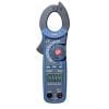


How to use REED R5020 AC Clamp Meter
Data Hold
While taking a measurement, press the Data Hold button to freeze the display. The HOLD indicator will also appear on the display. Press the Hold button again to resume measuring.
AC Current Measurements with REED R5020
Start using the REED R5020 and set the function switch to the 400 or 40A range. If the range needed is not known, select the higher range first then move to the lower range if necessary. Open the instrument’s jaw by pressing the trigger. Now just fully enclose one conductor and the R5020’s LCD will display the reading.
AC/DC Voltage Measurements
For voltage measurements you need to insert the black test lead into the negative COM terminal and the red test lead into the positive V terminal. Using the instrument rotation switch, choose V position, and depends on your measurements, select either AC or DC with the MODE button. Connect the test leads in parallel to the circuit under test. The LCD will display the reading.
Resistance Measurements with R5020 clamp meter
Make resistance measurements with our R5020 Reed Clamp Meter. Firstly, insert the black test lead into the negative COM terminal and the red test lead into the positive V terminal. Secondly, choose the Ω (ohm) position using the rotary switch. Now you can touch the test probe tips across the circuit or component under test. The rest of the circuit will not interfere with reading if you will disconnect one side of the device under the test. Read the measurements value on the instrument LCD display.
Diode and Continuity Measurements
For using this Reed R5020 instrument into Diode and Continuity electrical tests, first think you have to do is to connect the test lead correctly as following: the black test lead into the negative COM terminal and the red test lead into the positive V diode terminal. Turn the rotary switch to the Ω position and press the MODE button until the Diode Test indicator appears on the display. Touch the test probes to the diode under test. Forward voltage will indicate 0.4V to 0.7V. Reverse voltage will be indicated by “OL”. Shorted devices will indicate near 0mV and an open device will be indicated by “OL” in both polarities. For Continuity tests, if the resistance is < 150, a tone will sound.
Capacitance Measurements
Even if this R5020 was designed to work as clamp meter, the instrument can made Capacitance Measurements with precision and accuracy results. Same as any multimeter, disconnect power to the unit under test and discharge all capacitors before taking any capacitance measurements, remove the batteries and unplug the line cords. Using the R5020’s rotary function, switch to the CAP position. Connect the test leads as following: black test lead into the negative COM terminal and the red test lead into the positive V terminal. Touch the test leads to the capacitor to be tested and read the capacitance value on the display.
Frequency or % Duty Cycle measurements
The R5020 Clamp on meter must be used correctly to assure accuracy of the any frequency or % duty cycle measurements. The most important is to set the rotary function switch to the V position. Connect the black test lead into the negative COM terminal and the red test lead into the positive V terminal. Select Hz or % duty with the Hz/% button. Touch the test probe tips to the circuit under test. Read the frequency value on the display.
Temperature Measurements
One of the most great feature of this Clamp meter is that you can made also temperature measurements. For this kind of tests and to avoid electric shock, disconnect both test probes from any source of voltage before making a temperature measurement. Set the function switch to °C or °F and insert the Temperature Probe into the negative COM and the positive V terminals, making sure to observe the correct polarity.Touch the Temperature Probe head to the area to be measured. Keep the probe touching the part under test until the reading stabilizes (about 30 seconds). Read the temperature value on the display. To avoid electric shock, be sure the thermocouple has been removed before changing to another function.
Non-Contact AC Voltage Measurement
Touch the probe tip to the hot conductor or insert into the hot side of the electrical outlet. If AC voltage is present, the detector will light up. The conductors in electrical cord sets are often twisted. For best results, rub the probe tip along a length of the cord to assure placing the tip in close proximity to the live conductor. The detector is designed with high sensitivity. Static electricity or other sources of energy may randomly trip the sensor.
REED R5020 Specifications
- AC Current Range: 40.00, 400.0A
- AC Current Accuracy: ±(2.5% rdg. + 8 dgt.)
- DC Voltage Range: 400.0mV, 4.000, 40.00, 400.0, 600.0V
- DC Voltage Accuracy: ±(1.5% rdg. + 2 dgt.)
- AC Voltage Range: 4.000, 40.00, 400.0, 600.0V
- AC Voltage Accuracy: ±(1.8% rdg. + 8 dgt.)
- Resistance Range: 400.0Ω, 4.000, 40.00, 400.0kΩ, 4.000, 40.00MΩ
- Resistance Accuracy: ±(1.5% rdg. + 2 dgt.)
- Capacitance Range: 40.00, 400.0nF, 4.000, 40.00, 100.0μF
- Capacitance Accuracy: ±(3% rdg. + 5 dgt.)
- Temperature Range: -20.0 to 760.0°C (-4.0 to 1400.0°F)
- Temperature Accuracy: ±(3% rdg. + 5°C/9°F)
- Diode Test: Test current of 0.3mA typical;
- Open circuit voltage 1.5V DC typical
- Continuity Check: Threshold <150Ω; Test current <0.5mA
- Jaw Opening: 1.2” (30mm) maximum
- Power Supply: 2 x 1.5V “AAA” batteries
- Dimensions: 200 x 66 x 37mm
- Weight: 205g


Reviews
There are no reviews yet.